CNC Export
Generates the machining files for the panels in the model in SVG, DXF or G-code format: outer contour, cutouts, pockets, grooves, rabbets, drillings and engravings.
How it works
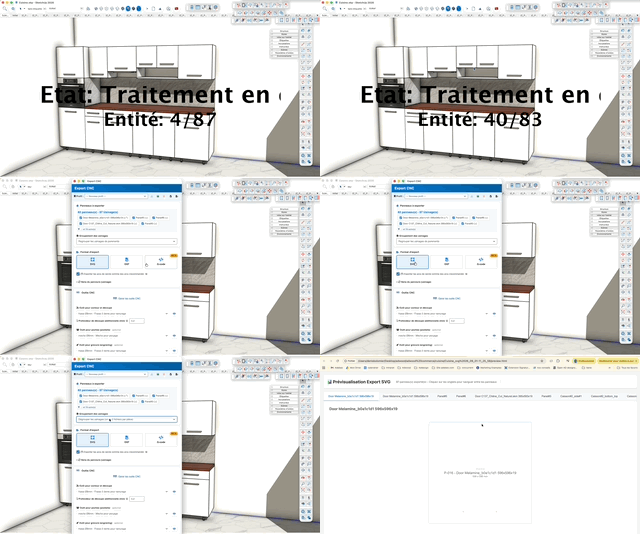
- Optionally select the parts to machine, then launch the command from the CNC toolbar (or the Adwood menu)
- Wait while the panels are prepared; a click in the view interrupts the processing in progress
- In the window, check the list of panels to export and the grouping mode
- Choose the export format (SVG, DXF or G-code) and set its options
- Assign at least a tool for contour and cut-out; pockets and engraving are optional
- Set the export folder if you do not want to write next to the SketchUp file
- Click Export
A profile stores all of these settings and recalls them from one model to the next.
Profile bar
At the top of the window, it remembers a complete set of settings (format, options, tools, folder).
- Profile (list) — “New profile” as long as no profile is selected
- Load this profile (down arrow) — applies the selected profile to the whole window
- Save current profile (floppy disk) — asks for a name and saves the current settings; reusing an existing name overwrites it
- Delete this profile (trash) — deletes the selected profile, after confirmation
- Import from file / Export to file (on the right) — exchanges profiles as a
.json file, to share them between workstations or workshops
“Panels to export” section
- Entire model / Selection (radio buttons) — only appears if a selection existed when the command was launched; each choice shows its panel count
- Counter — number of checked panels and total of the corresponding machinings
- Panel list — one checkbox per part, all checked by default. Beyond five parts the list is collapsed: click “… and N more” to unfold it
- Renumber all (button, right of the label field) — renumbers every part in the model. Numbers name the CNC files: the window closes, renumbering opens, then you run the export again.
One last setting, the Part label, applies to the vector formats only (SVG and DXF): it chooses the text engraved at the centre of each part. G-code carries none — it only has comments.
- None — no text in the file
- Part label (default) — the full name of the part
- Label + dimensions — the name, then an “L x W” line in the drawing unit
The text size is derived from the length of the label and the room available: the label is rotated 90° on parts taller than wide, and it is omitted on parts where it would become unreadable, rather than overflowing the outline. Choose None if your CAM software derives the panel size from the drawing extents (VCarve for instance): a text then counts as material.
In G-code this setting is locked on None and the menu is greyed out: a program carries comments only. Your choice is kept and comes back as soon as you switch to DXF or SVG.
“Export format” section
Three buttons — SVG, DXF, G-code — only one of which is active at a time. The chosen format drives the display of the options below: whatever does not apply is hidden.
SVG
Format for checking and simple cutting: a to-scale vector drawing readable by any cutting or drawing software. A preview opens in the browser once the window is closed.
A single format-specific option: the Part label described above. Otherwise only the common settings apply (panels, grouping, arcs, toolpath direction, through machinings, tools, export folder).
DXF
Exchange format for wood CAM software (woodWOP, BiesseWorks, WoodStore, CADWork, WoodCAD|CAM…), which selects the tool from the layer name and colour.
- DXF version:
- R2000 (AC1015) — recommended, colored layers, LWPOLYLINE; suits every modern CNC program
- R14 (AC1014) — POLYLINE/VERTEX/SEQEND, for older machines or proprietary controllers
- Help by brand (link) — table of recommended versions depending on the software or machine
- Apply tool offset — checked, Adwood computes the tool-center path and the file already contains the radius offset; unchecked, the path follows the nominal contour of the part exactly
G-code (beta)
Complete machining program, directly executable by the machine. This is the most configurable format: the settings below only appear when it is selected.
Its own settings — safety, spindle, tool change, header and dialect — are gathered in the “Machine” section at the bottom of the window.
Batch and destination
Where and in what form the files are written.
- Machining grouping (list):
- Separate machinings — one file (or two, face and back) per part
- Group facing machinings — all parts nested in a single file, face side
- Group back machinings — same on the back side
- Nesting clearance (mm) — only visible in grouped mode. The actual spacing between parts equals the tool diameter plus this clearance (Ø8 mm tool + 0.2 mm clearance = 8.2 mm)
- Browse… — chooses the destination folder for the files
- Red cross — clears the choice and returns to the default behaviour: the files are written to the folder of the SketchUp file
- Generate an operator summary (.txt) — summary sheet of tools and operations to hand to the workstation
- Machine-safe filename — no accents or spaces
Machining
Options are grouped by machining type: each group holds the tool, the path direction and the settings specific to it.
- Export circular arcs as arcs (recommended) — checked, arcs are output as true arcs (G2/G3 in G-code, A command in SVG); unchecked, they are output as line segments, exactly as in SketchUp
- G-code arc format — R (radius, recommended) or I/J (center vector)
- Manage CNC tools (button) — opens the tool manager, where the router bits, drill bits and engravers of your inventory are created and edited; when it closes, the three lists below are rebuilt: a tool you created shows up at once, a tool you deleted is cleared from the selection, without touching the checked panels or the other settings
- Eye (to the right of each list) — unfolds the tool data sheet: type, diameter, description, speed XY, speed Z, rotation
Contour and cut-outs
- Tool for contour and cut-out — required: without it the Export button stays inactive
- Additional cutting depth (mm) — extra depth below the panel thickness to guarantee a clean through cut (0.2 mm by default)
- Machining strategy (G-code only):
- Progressive depth-first (default) — thick panels, medium rigidity
- Progressive linear — simultaneous depth and offset progression
- Direct — a single full pass, for thin panels and rigid machines
- Max depth per pass (mm) (G-code, except the Direct strategy) — 3 mm per pass on a 19 mm panel gives 7 passes
- Apply tool offset — offset computed by the software (works on any machine)
- Cutter compensation (G-code) — None (software offset), Left — G41 or Right — G42: the machine then applies the radius through its offset register (D). Mutually exclusive with the software offset on the outer contour: enabling G41/G42 disables it automatically, otherwise compensation would be applied twice
- Path direction — outer contour (counter-clockwise by default) and cut-outs (clockwise): this is the climb-milling convention.
Drilling
- Use drilling cycles G81/G83 — instead of expanded G0/G1 moves
Cabineo (Lamello) connectors are recognised from their geometry: a body whose bottom is a cloud of 2 or 3 overlapping Ø15 circles, usually surrounded by a shallow flange recess. Recognition still works when SketchUp has exploded the arcs. The outer contour always follows the nominal perimeter of the part: the connector notch on the edge never appears in the outer contour, it is machined from the face.
The Cabineo connectors list selects the machining strategy, to be matched with the workshop method:
- 3 × Ø15 drillings + flange pocket (recommended) — the body circles are output as drillings at the body depth (
DRILL_… layers, G81/G83 cycles or helical interpolation in G-code); the flange is output as a closed pocket (CABINEO_RECESS_<tool>_<depth>). This is the "drilling" variant documented by Lamello
- 2 milled pockets — the body is output as a pocket with a cloud-shaped contour (
CABINEO_BODY_<tool>_<depth>, arcs preserved) and the flange as a second pocket; no drilling. For workshops that rout everything with a straight cutter
- Machine macro / aggregate — one segment per connector, from the mouth on the edge to the bottom of the body (
CABINEO_MACRO_<depth>): it gives position and orientation to the CAM macro or the dedicated aggregate. No toolpath is generated; in G-code only a CABINEO X… Y… ANGLE… DEPTH… comment is written
Depths (body and flange) are read from the model and written into the layer names, in millimetres (10_8 = 10.8 mm).
Groove, rabbet, pocket
- Pocket tool — optional; it also serves rabbets and grooves.
- Extend through machinings — unchecked by default. When checked, grooves and rabbets that break out on an edge have their toolpath extended beyond the face of the part, so the cutter fully clears the material: no exit fillet is left behind, and when nesting the profiling pass no longer runs over a groove that was not cleared. Blind machinings, which close on a real edge, are never modified
- Exit clearance (mm) — added to the tool radius: overrun = radius + clearance. The field stays greyed out while the option is unchecked. In grouped (nesting) mode, keep the overrun below half the nesting clearance, otherwise the cutter cuts into the neighbouring part
- Path direction — pockets, rabbets and grooves share a single setting (clockwise by default).
Engraving
- Engraving tool — optional.
- Path direction — applies to inner contours (clockwise by default).
An inner contour is a closed shape drawn on the face: it is engraved at the engraving tool’s depth, without going through the part. A hole that passes right through the panel is a cut-out, machined in the “Contour and cut-outs” group at full thickness.
Machine
Post-processor settings, shared by every part. The section only appears in G-code mode and stays collapsed: set it once per machine, then recall it from a profile.
Safety and dry run
- Z1 - Safety plane (mm) — height of rapid moves (G0) above the part between two operations
- Enable M7 (blow / mist) and Enable M8 (suction / coolant) — each with a customizable label and code, to match the actual wiring of the machine
- Auxiliary stop code — sent at the end of the program if M7 or M8 is active (M9 by default)
- Dry-run mode — program without M3 and without M7/M8, at reduced speeds; the speed factor (0.3 = 30%) sets the slowdown
Tool change
- Automatic tool magazine (ATC) — checked, the machine changes tools on its own with M6; unchecked, the program stops (M0) at every change for a manual operation
- Tool change format —
T1 M6, M6 T1, T01 M06 or none
- Include tool name as comment — then choose the template:
(Tool: Fraise_D8), (Fraise_D8) or ; Tool: Fraise_D8
- Tool length compensation —
G43 H{n}, G43 H{n} Z{z1} or none
- H number identical to T number — otherwise enter an H offset
- Spindle / speed order —
S18000 M3 or M3 S18000
- Delay after spindle start — none,
G4 P1, G4 P2 or a custom command
- Generate one file per tool — for machines without an automatic tool changer
5-axis machine
- Not a 5-axis machine — no command added (3-axis machines)
- B+C, A+C, A+B — inserts
G0 B0 C0, G0 A0 C0 or G0 A0 B0 at the top of the program to bring the tool back to vertical
- Custom (free field) — your own line, for example
M129 G0 B0 C0 to disable RTCP before the reset
Program
- Full modal header — writes
G90 G94 G17 G21 G40 G49 G80… at the beginning of the file
- Output units — millimeters (G21) or inches (G20)
- Work coordinate — none, G54, G55 or G56
- End of program code — M30 (recommended), M2 or custom
- Return height at end of program — safety height (
G0 Z{Z1}), machine zero (G53 G0 Z0) or none
- XY return at end of program — none, part origin, parking position (X/Y to enter) or machine zero
- Insert an information block — descriptive header at the beginning of the file (part, tools, dimensions)
Dialect
- Comment type — semicolon, parentheses, or no comments
- Clean special characters — strips accents and Unicode from the comments
- Decimal places — 2 (12.50) or 3 (12.500)
- Remove trailing zeros — writes 12.5 instead of 12.500
- Number the lines — with an increment of 1, 5 or 10
Window footer
- Export — starts the generation. The button stays inactive as long as no contour tool is selected or no panel is checked
- Cancel — closes the window without writing anything
Keys
- Enter = start the export (if the Export button is active)
- Click in the view = interrupt the preparation of the panels before the window opens
- Esc = Cancel the operation
Tips
- Create one profile per machine: format, tools, tool change and auxiliary codes are then fixed once and for all, and the exported
.json file can be shared with the workshop
- Select the parts in the model before launching the command: the “Selection” choice then appears in the window
- Export to SVG first to visually check the contours and drillings, then run the export again as G-code once the result is validated
- When in doubt about the DXF version, stay on R2000: every recent wood CAM program accepts it
- Never enable G41/G42 together with a software offset: the radius would be counted twice — the window handles this, but check the result on the machine
- Before a first program on an unknown machine, enable dry-run mode: the toolpath runs without spindle or suction, at reduced speed
- Grouped mode (nesting) only makes sense if all the checked parts share the same board and the same thickness
- The through-machining overrun belongs to the machine, not to the part: store it in the profile, with a clearance compatible with the nesting clearance you use most often
- If your CAM software computes the panel size from the drawing, set the label to “None”: otherwise the centre text is counted as material